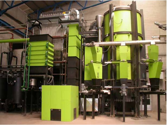
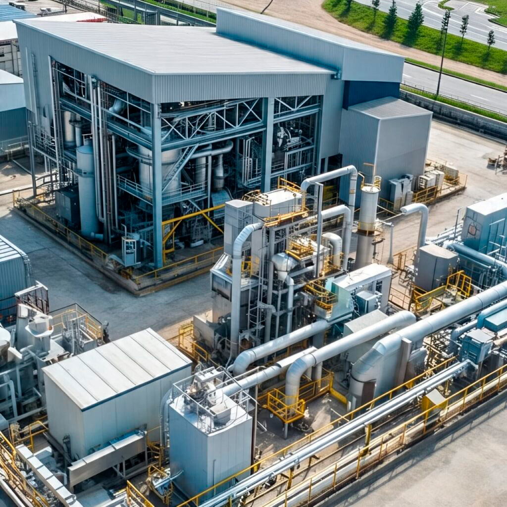
ENTRAINED FLOW GASIFICATION PLANT WITH RSU.
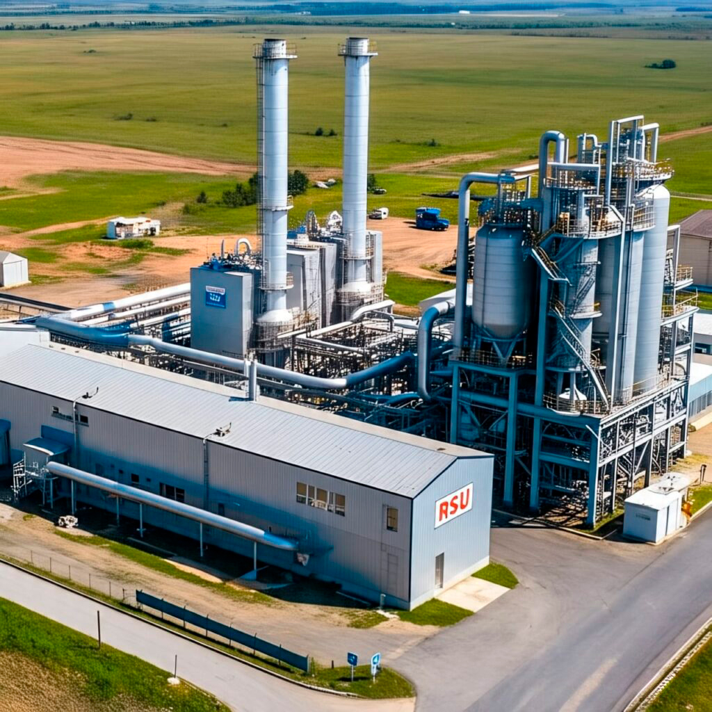
FLOW-ENTRAINED GASIFICATION PLANT; is an advanced technology used to convert Carbonaceous feedstocks, such as Coal, Biomass or Municipal Solid Waste, into SYNGAS, mainly composed of Carbon Monoxide (CO), Hydrogen (H₂) and other gases. This process is carried out at high temperatures between 1,300 °C to 1,600 °C; and pressures between 20 – 80 BAR, with very short residence times, in just 2 to 3 seconds.
MAIN CHARACTERISTICS
- HIGH EFFICIENCY:
Almost complete conversion of Carbon into SYNGAS. - FLEXIBILITY OF RAW MATERIAL:
It can process Coal, Biomass, Heavy Oil or Municipal Solid Waste. - HIGH TEMPERATURES:
Prevents the formation of tar and other unwanted by-products. - SCALABILITY: We can adapt both in Industrial Plants and in small-scale projects.
MAIN COMPONENTS
- FEEDING SYSTEM:
a. Pulverization of the Feedstock (Coal, Biomass, or MSW) into fine particles (<100 μm).
b. Injection into the Reactor by means of a Nitrogen carrier Gas or Carbon Gas (N₂ or CO₂). - GASIFICATION REACTOR (GASIFIER):
a. Partial combustion with pure oxygen (O₂) or SIMPLE AIR.
b. Dominant reactions:
I. Oxidation: (C + frac {1}{2}O2 right arrow CO)
II. Reduction: (C + CO_2 right arrow 2 CO) (Boudouard)
III. Steam Gasification: (C + H2O right arrow CO + H2) - SYNGAS COOLING AND CLEANING SYSTEM:
a. Rapid cooling to prevent gas recombination.
b. Removal of particles (filters or cyclones) and contaminants (H₂S, COS, HCl). - SLAG TREATMENT:
a. The ashes melt at high temperatures, forming non-toxic vitrified slag. - EAT RECOVERY:
a. Steam generation for turbines or use in industrial processes.
- FEEDING SYSTEM:
ADVANTAGES
- A high purity SYNGAS (low in methane and tars).
- Plant is suitable for CO₂ capture (PRE-COMBUSTION).
- Integration with chemical processes (Fischer-Tropsch, hydrogen, ammonia).
CHALLENGES
- High cost of Oxygen, IF O₂ is used instead of RUNNING AIR.
- It requires finely ground raw materials.
- Sensitivity to fuel properties (Ash, Moisture).
APPLICATIONS
- Power generation (IGCC Combined Cycles).
- Production of liquid fuels, such as Synthetic Diesel.
- Manufacture of Hydrogen or Basic Chemicals.
- Production of Agricultural Fertilizers.
PROCESS OF A IN FLOW-ENTRAINED GASIFICATION PLANT
- RECEPTION AND PREPARATION OF THE MATERIAL.
a. Type of raw material: Coal, dry biomass, plastics, industrial waste or pre-treated garbage.
b.Preparation stages:
c. Drying: Humidity is reduced to <10%.
d. Crushing and grinding: The material is turned into a fine powder (size <100 μm).
e. Silo storage: For continuous feeding to the system. - FEEDING THE REACTOR
a. Pressurized Feed System: Introduces dry powder to the reactor under high-pressure conditions.
b. It is mixed with a Gasifying Agent: pure oxygen, air, or water vapor (or a combination).
c. The mixture: enters the reactor through special injectors or burners. - GASIFICATION IN THE ENTRAINED FLOW REACTOR
a. It occurs at high temperatures (1200–1600 °C) and pressures (up to 40 bar).
b. The dust is carried away by the flow of the raising agent in a Flow-entrained.
c. Main reactions:
I. C + 1/2O₂ ⭢ CO (Partial Combustion)
II. C + H₂O ⭢ CO + H₂ (Gasification)
III. CO + H₂O ⭤ CO₂ + H₂ (Water-Gas Displacement Reaction)
IV. A HOT GAS rich in H₂ and CO (syngas) is generated.
MAIN PROCESS
RECEIVING AND PREPARING MSW (EQUIPMENT & FUNCTION)
- Receiving Hoppers
Reception of Waste, Coal, Biomass, Plastics. - Shredders / Mills
Reduction in material size (<100 μm). - Heat dryers
Moisture removal (by hot air, steam or hot gases).
- Screw feeders and feeders
Precise fuel feeding to the grinding or storage system. - Storages
Intermediate storage of dry and pulverized fuel. - Inerting system (N₂ or CO₂)
Prevents explosions in silos and dust transport lines.
REACTOR FEEDING SYSTEM (EQUIPMENT & FUNCTION)
- Double Airlock Valves / Rotary Valves
Pressurized system isolation. - Special injectors or burners
They introduce the mixture of fuel + gasifying agent into the reactor. - Mass flow dispensers
They control the powder feed rate. - Oxygen/air compressors or blowers
They provide pressure and flow to the raising agent.
REACTOR (EQUIPMENT & FUNCTION)
- Cylindrical steel reactor with refractory lining
Main area where thermochemical reactions occur. - Oxygen/Steam Burners
They control the internal temperature. - Instrumentation (thermocouples, pressure gauges, gas analyzers)
Monitoring of pressure, temperature and composition of the gas. - Slag chamber
Collect molten slag that comes out by gravity.
SLAG MANAGEMENT (EQUIPMENT & FUNCTION)
- Slag coolers (quenching or exchanger)
These solidify molten slag. - Slag conveyor
Remove the solid residue from the bottom of the reactor. - Collection hoppers
These store the slag for disposal or reuse.
SYNGAS COOLING (EQUIPMENT & FUNCTION)
- Heat exchangers (shell & tube or gas-gas type)
They recover energy from hot gas. - Quench tower
Lower the temperature of the syngas quickly using water.
GAS CLEANING SYSTEM (EQUIPMENT & FUNCTION)
- Cyclones
Removal of coarse particles. - Wet or dry scrubbersThese remove acidic compounds (HCl, HF, SO₂).
- Ceramic or fabric filters
These remove fine particles from the gas. - Adsorbent bed reactors (ZnO, activated carbon, etc.)
These remove H₂S, mercury, other contaminants. - Compressors or blowers
These transports and pressurizes clean syngas.
PROCESS WATER TREATMENT (EQUIPMENT & FUNCTION)
- Phase separators
These remove oils or suspended solids. - Chemical neutralization tanks
These adjust pH and remove contaminants. - Filters and reverse osmosis systems (if required)
These purify water for recirculation or safe discharge.
USING THE SYNGAS (EQUIPMENT & FUNCTION)
- Gas turbines or engines
Electricity generation. - Fischer-Tropsch reactors
Production of liquid fuels. - Purificators PSA (Pressure Swing Adsorption)
Production of pure Hydrogen. - Industrial boilers or burners
Thermal use of syngas.
SYSTEM AUXILIARY (EQUIPMENT & FUNCTION)
- Distributed Control System (DCS)
Real-time automation and monitoring. - Electrical System (Transformers, UPS)
Power and energy backup. - Fire safety and extinguishing systems
Accident prevention. - Ventilation and exhaust system
Safety of the work environment.