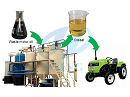
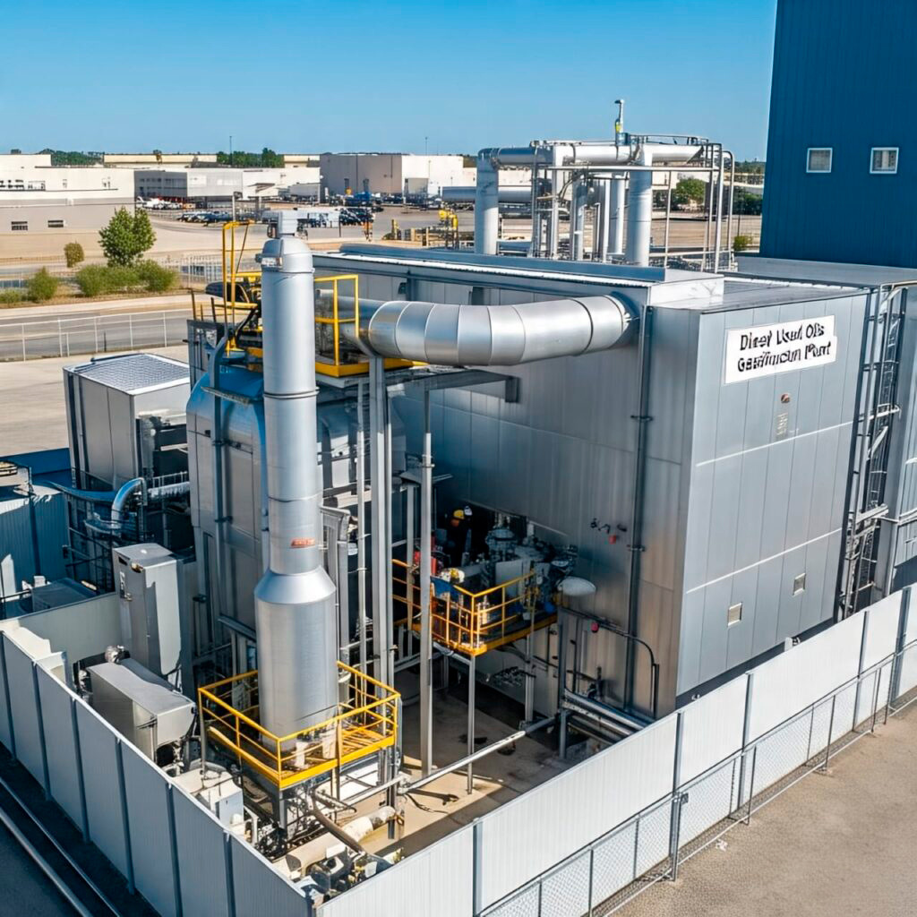
GASIFICATION PLANT TO TRANSFORM USED OILS INTO DIESEL
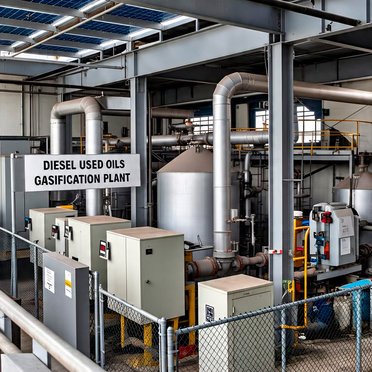
It is a sustainable solution for the production of renewable Fuels.
This process converts fatty waste into a high-quality fuel using technologies and processes to convert Oils into Diesel, such as these technologies:
- TRANSESTERIFICATION (Biodiesel).
- PYROLYSIS
- GASIFICATION
ADVANTAGES VS. ALTERNATIVES
- TRANSESTERIFICATION
The product that is obtained is the Biodiesel has a Medium Complexity. - PYROLYSIS
The product that is obtained is the Bio-oil Refinable has a Medium-High Complexity. - GASIFICATION
The product that is obtained is the Synthetic-Diesel has a High Complexity.
MAIN CHARACTERISTICS
- HIGH EFFICIENCY: Almost complete conversion of Carbon into SYNGAS.
- FLEXIBILITY OF RAW MATERIAL: It can process Coal, Biomass, Heavy Oil or Municipal Solid Waste.
- HIGH TEMPERATURES: Prevents the formation of tar and other unwanted by-products.
- SCALABILITY: We can adapt both in Industrial Plants and in small-scale projects.
MAIN COMPONENTS
- FEEDING SYSTEM:
a. Pulverization of the Feedstock (Coal, Biomass, or MSW) into fine particles (<100 μm).
b. Injection into the Reactor by means of a Nitrogen carrier Gas or Carbon Gas (N₂ or CO₂). - GASIFICATION REACTOR (GASIFIER):
a. Partial combustion with pure oxygen (O₂) or SIMPLE AIR.
b. Dominant reactions:
I. Oxidation: (C + frac {1}{2}O2 right arrow CO)
II. Reduction: (C + CO_2 right arrow 2 CO) (Boudouard)
III. Steam Gasification: (C + H2O right arrow CO + H2) - SYNGAS COOLING AND CLEANING SYSTEM:
a. Rapid cooling to prevent gas recombination.
b. Removal of particles (filters or cyclones) and contaminants (H₂S, COS, HCl). - SLAG TREATMENT:
a. The ashes melt at high temperatures, forming non-toxic vitrified slag. - HEAT RECOVERY:
a. Steam generation for turbines or use in industrial processes.
ADVANTAGES
- A high purity SYNGAS (low in methane and tars).
- Plant is suitable for CO₂ capture (PRE-COMBUSTION).
- Integration with chemical processes (Fischer-Tropsch, hydrogen, ammonia).
CHALLENGES
- High cost of Oxygen, IF O₂ is used instead of RUNNING AIR.
- It requires finely ground raw materials.
- Sensitivity to fuel properties (Ash, Moisture).
APPLICATIONS
- Power generation (IGCC Combined Cycles).
- Production of liquid fuels, such as Synthetic Diesel.
- Manufacture of Hydrogen or Basic Chemicals.
- Production of Agricultural Fertilizers.
PROCESS OF A IN FLOW-ENTRAINED GASIFICATION PLANT
- RECEPTION AND PREPARATION OF THE MATERIAL.
a. Type of raw material: Coal, dry biomass, plastics, industrial waste or pre-treated garbage.
b. Preparation stages:c. Drying: Humidity is reduced to <10%.
d.Crushing and grinding: The material is turned into a fine powder (size <100 μm).
e. Silo storage: For continuous feeding to the system.
- FEEDING THE REACTOR
a. Pressurized Feed System: Introduces dry powder to the reactor under high-pressure conditions.
b. It is mixed with a Gasifying Agent: pure oxygen, air, or water vapor (or a combination).
c. The mixture: enters the reactor through special injectors or burners. - GASIFICATION IN THE ENTRAINED FLOW REACTOR
a. It occurs at high temperatures (1200–1600 °C) and pressures (up to 40 bar).
b.The dust is carried away by the flow of the raising agent in a Flow-entrained.
c. Main reactions:
I. C + 1/2O₂ ⭢ CO (Partial Combustion)
II. C + H₂O ⭢ CO + H₂ (Gasification)
III. CO + H₂O ⭤ CO₂ + H₂ (Water-Gas Displacement Reaction)
IV. A HOT GAS rich in H₂ and CO (syngas) is generated.
MAIN PROCESS
RECEIVING AND PREPARING MSW (EQUIPMENT & FUNCTION)
- Receiving Hoppers
Reception of Waste, Coal, Biomass, Plastics. - Shredders / Mills
Reduction in material size (<100 μm). - Heat dryers
Moisture removal (by hot air, steam or hot gases). - Screw feeders and feeders
Precise fuel feeding to the grinding or storage system. - Storages
Intermediate storage of dry and pulverized fuel. - Inerting system (N₂ or CO₂)Prevents explosions in silos and dust transport lines.
REACTOR FEEDING SYSTEM (EQUIPMENT & FUNCTION)
- Double Airlock Valves / Rotary Valves
Pressurized system isolation. - Special injectors or burners
They introduce the mixture of fuel + gasifying agent into the reactor. - Mass flow dispensers
They control the powder feed rate. - Oxygen/air compressors or blowers
They provide pressure and flow to the raising agent.
REACTOR (EQUIPMENT & FUNCTION)
- Cylindrical steel reactor with refractory lining
Main area where thermochemical reactions occur. - Oxygen/Steam Burners
They control the internal temperature. - Instrumentation (thermocouples, pressure gauges, gas analyzers)
Monitoring of pressure, temperature and composition of the gas. - Slag chamber
Collect molten slag that comes out by gravity.
SLAG MANAGEMENT (EQUIPMENT & FUNCTION)
- Slag coolers (quenching or exchanger)
These solidify molten slag. - Slag conveyor
Remove the solid residue from the bottom of the reactor. - Collection hoppers
These store the slag for disposal or reuse.
SYNGAS COOLING (EQUIPMENT & FUNCTION)
- Heat exchangers (shell & tube or gas-gas type)
They recover energy from hot gas. - Quench tower
Lower the temperature of the syngas quickly using water.
GAS CLEANING SYSTEM (EQUIPMENT & FUNCTION)
- Cyclones
Removal of coarse particles. - Wet or dry scrubbers
These remove acidic compounds (HCl, HF, SO₂). - Ceramic or fabric filters
These remove fine particles from the gas. - Adsorbent bed reactors (ZnO, activated carbon, etc.)
These remove H₂S, mercury, other contaminants. - Compressors or blowers
These transports and pressurizes clean syngas.
PROCESS WATER TREATMENT (EQUIPMENT & FUNCTION)
- Phase separators
These remove oils or suspended solids. - Chemical neutralization tanks
These adjust pH and remove contaminants. - Filters and reverse osmosis systems (if required)
These purify water for recirculation or safe discharge.
USING THE SYNGAS (EQUIPMENT & FUNCTION)
- Gas turbines or engines
Electricity generation. - Fischer-Tropsch reactors
Production of liquid fuels. - Purificators PSA (Pressure Swing Adsorption)
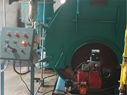
Production of pure Hydrogen. - Industrial boilers or burners
Thermal use of syngas.
SYSTEM AUXILIARY (EQUIPMENT & FUNCTION)
- Distributed Control System (DCS)
Real-time automation and monitoring. - Electrical System (Transformers, UPS)
Power and energy backup. - Fire safety and extinguishing systems
Accident prevention. - Ventilation and exhaust system
Safety of the work environment.
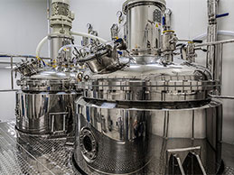
VERTICAL TANKS FOR SYNTHETIC GASOLINE + BY PRODUCTS DIESEL, GASES
a. With double wall or secondary containment and prevent leaks into the environment, in case of rupture of the primary tank.
b. The Protect the environment.
c. It can be made of stainless-steel fiber, higher corrosion resistance.
d. With a capacity of 10,000 liters.
e. Basic Components
I. Cylindrical steel body.
II. Flat or conical bottom.
III. Fixed or floating roof.
IV. Manhole, valves, sensors, level gauges, vents (vending).
V. Fire protection system (foam, water, sprinklers).
f. Advantages of Vertical Tanks
I. Make better use of the space in the floor plan.
II. Facilitate drainage by gravity.
III. Lower evaporation compared to horizontal tanks.
IV. Increased capacity without taking up a lot of land.
g. Safety Considerations
I. Fire suppression system.
II. Leak detection.
III. Grounding (atmospheric discharges).
IV. Vapor and pressure monitoring.
V. Secondary containment barriers (dikes or perimeter walls).